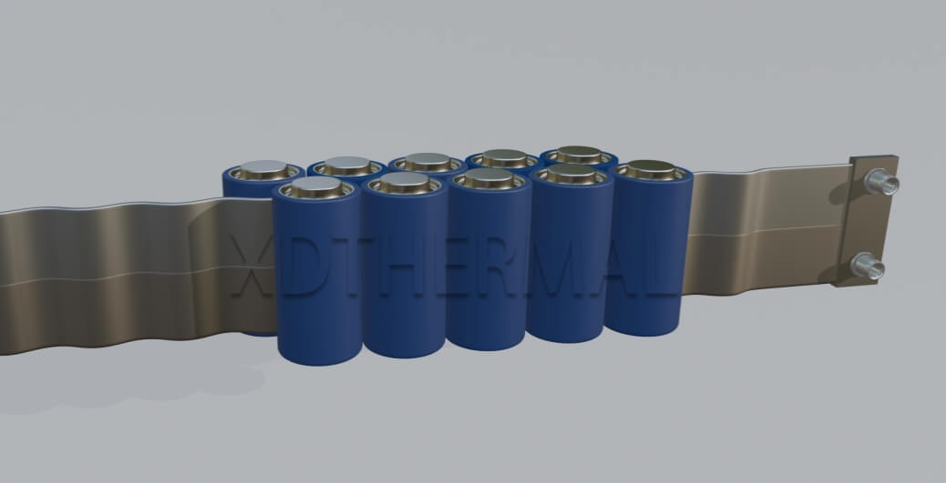
In many battery cooling projects, I often come across clients with very specific requirements: they want the system to be highly efficient in cooling, structurally compact, and preferably able to fit closely around cylindrical cells. That’s when the serpentine tube becomes a very common and practical choice.
It’s a type of curved tubo de refrigeración líquida that can flexibly follow the layout of the cells and carry heat away evenly from the sides. Common sizes like 1865, 2170, 4680, and 4695 are generally all compatible. With its large contact area, flexible routing, and strong adaptability, it’s ideal for systems where space is tight but efficient heat transfer is still a must. Such systems often operate under demanding conditions where even small inefficiencies can have noticeable impacts on performance.
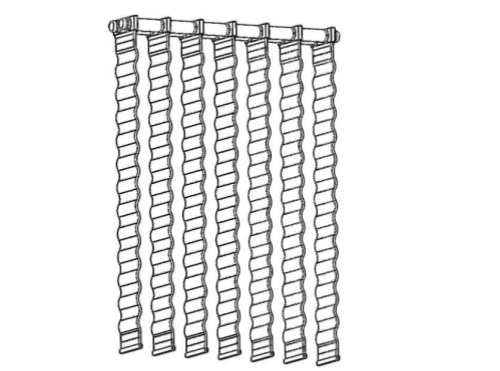
That said, the advantages of serpentine tubes come hand in hand with certain challenges. Because of their many bends, long flow paths, and complex structures, they often bring up an issue that’s easy to overlook but actually quite critical—pressure drop. For liquid to flow smoothly through the entire tubing, it needs to overcome quite a bit of resistance. Many designs that look thermally sound on paper end up getting stuck during the testing phase, simply because the pressure drop wasn’t calculated properly.If not managed carefully, this resistance can limit flow rate, reduce thermal uniformity, and impair the overall system’s effectiveness.
So in this article, I’d like to start from real-world experience and talk about what actually affects pressure drop in serpentine tubes—and more importantly, what we can do during the design stage to optimize for better system performance and controllability.
When it comes to pressure drop, many people don’t pay much attention to it during the early design phase. Sometimes, even when working on cold plate design, this step is simply skipped. But once the system starts running, related issues tend to show up gradually. Simply put, pressure drop is the resistance the coolant encounters while flowing through the channel, typically reflected as the pressure difference between the inlet and outlet. This pressure differential is influenced by geometry, flow speed, fluid properties, and system layout. The larger the difference, the more restricted the flow becomes, and that can negatively affect the cooling performance.
I’ve seen a few projects where the initial thermal design looked perfectly fine—materials were well chosen, contact area was accounted for—but during testing, we saw unexpectedly high temperature rise. Even though the thermal simulations appeared accurate, real-world test data showed clear deviations. After digging into it, we realized that an excessive pressure drop was causing the flow rate to drop, making it harder for the heat to be carried away in time, which in turn led to a wider temperature gap across the system.
With serpentine-type liquid cooling tubes, the impact is even more noticeable—because of their frequent bends and relatively long paths, pressure drop tends to be more pronounced. This structure is actually quite common in many current cold plate thermal management designs, and if pressure drop isn’t properly evaluated in the early stages, it could end up limiting the system’s performance once deployed.
So in my view, pressure drop is not a parameter that can be ignored. It’s closely tied to how the entire cold plate system operates. Especially when dealing with custom requirements, factoring pressure drop into the early stages of designing a customized liquid cooling tube solution can really help improve the overall reliability and suitability of the system. It’s one of those factors that, while sometimes hidden, can significantly influence thermal efficiency and component lifespan over time.
Since pressure drop isn’t something we can afford to ignore, what exactly affects it? Based on the projects I’ve been involved in, structure and flow rate are two key factors that usually take priority during the early design phase.
Let’s start with the structure itself. Pressure drop is closely related to the internal cavity size of the flattened serpentine tube. The smaller the internal space, the faster the liquid flows, and the greater the friction between the fluid and the tube wall—this in turn increases overall flow resistance. This kind of design is fairly common when trying to achieve compact, tightly fitted cold plate structures. However, even small dimensional changes in channel height or width can lead to exponential differences in flow resistance, especially under turbulent conditions.But even then, it’s important to strike a proper balance between dimensions and pressure drop.
Next is the total path length. The longer the serpentine route, the greater the distance the coolant has to travel, and the more frictional losses it will accumulate along the way. If the path length isn’t reasonably controlled, the cumulative effect of pressure drop can become increasingly significant across the system. This is particularly relevant in high-power applications or large modules, where excessive lengths can lead to uneven flow distribution.
Another factor is the number of bends. When the structure has frequent curves and directional changes, each change in flow direction creates local turbulence, which adds extra resistance. These kinds of localized losses become more noticeable in designs with many bends or in space-constrained systems, and they’re definitely something that should be closely evaluated during modeling or simulation. Even seemingly minor changes in bend radius or entry angle can result in sharp increases in localized pressure loss.
In addition, flow rate is also an important factor influencing pressure drop. As flow speed increases, the resistance the liquid needs to overcome also grows, which means more kinetic energy is consumed and the pressure drop level rises. This is especially common in cases where the flow rate fluctuates or when high heat transfer is required. So during the early stages of cold plate design, it’s important to assess not just the structure, but also how it interacts with actual operating flow rates.Designs that are marginally acceptable at low flow rates can become problematic at higher volumes, particularly if the system experiences pulse-like or transient flow behaviors.
Besides that, the physical properties of the coolant can also impact pressure drop. Things like viscosity, density, and temperature can all affect how the fluid behaves, which in turn influences its stability and resistance as it flows through the channels.For instance, under lower temperatures, increased viscosity can drastically increase flow resistance, while at higher temperatures, reduced viscosity might cause undesirable flow instability or cavitation.
Aside from these main factors, there are also some variables that are easy to overlook but still matter—such as the roughness of the inner tube walls, the way the serpentine tube is installed, or how support structures are arranged. These details might not always show up clearly on a drawing, but they definitely influence how the coolant flows during real-world assembly and operation.Poor installation angles, misalignment, or tube sagging can also induce pressure differentials, which are not accounted for in ideal simulations but show up during testing.
That’s why, when we’re working on cold plate design for thermal management or a customized liquid cold tube solution, we usually help clients evaluate everything from structure and flow to installation layout based on their product’s actual application needs. This ensures the design is not only practical and stable, but also truly fit for purpose. Such comprehensive consideration helps minimize surprises during validation, saving both time and cost.
These little things that seem like minor details can actually have a big impact on whether the entire system can run stably. Cold plate design isn’t just about drawing a few flow channels—it’s really about an entire set of cold plate technology working behind the scenes. That includes how the heat transfer paths are laid out, whether the liquid can flow smoothly, whether the structure is easy to manufacture, and most importantly—whether the whole thing truly meets the actual usage requirements.From simulation accuracy to manufacturing tolerances, every small choice made during design can affect system reliability over the full product lifecycle.
So whenever I’m dealing with a custom request, I usually start the conversation with the client by looking at the actual application scenario. For example, is this system going into a commercial vehicle, or is it being used in an energy storage setup? What are the on-site flow conditions? Are there space constraints? All of these factors will directly affect how we evaluate the liquid cooling path and pressure drop performance later on. Only when we take all these real-world conditions into account can we properly balance structure, pressure drop, and system efficiency in a custom serpentine tube design—and make sure the cooling solution is practical, stable, and truly usable.