In recent years, the deployment of solar panels has surged, and I’ve been genuinely impressed by the pace of growth in the photovoltaic (PV) market. A report from Fraunhofer ISE shows that from 2014 to 2024, global PV installations grew at a compound annual growth rate (CAGR) of 27%. It’s clear that the pursuit of more efficient solar energy utilization has become a strong and undeniable trend.
From my work, I’ve also noticed that modern PV systems are no longer used solely for power generation. In industrial parks, agricultural greenhouses, and commercial buildings, users increasingly require both electricity and thermal energy. As a result, more projects are turning to photovoltaic thermal (PVT) systems, which generate electricity and heat simultaneously through a single system—maximizing the value of each solar panel.
However, to truly achieve this “dual output” of electricity and heat, the cooling system must be up to the task. That’s where the PVT liquid cooling plate heat exchanger becomes essential. It needs to manage the PV module’s temperature while efficiently transferring heat for secondary utilization.
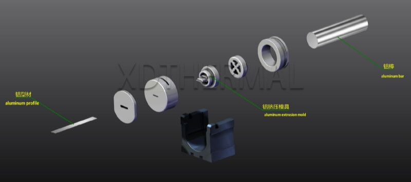
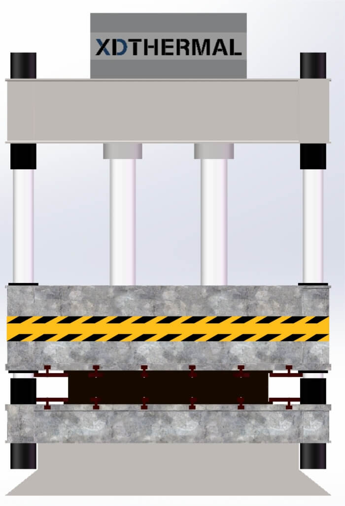
In my experience, PVT heat exchanger design is far from simple. The routing of flow channels, material selection, and pressure drop control all influence overall system efficiency. Manufacturing methods are just as critical. For example, we frequently use stamping processes or opt for extrusion cooling plate structures that are well-suited for standardized mass production. Every detail affects the final system performance.
When designing a PVT liquid cooling plate, the flow channel layout is often one of the first things to determine. Though it may sound like a matter of “where the water goes,” it directly impacts heat exchange efficiency, temperature distribution, and system stability. Based on my experience, flow channel design usually starts with a few core areas:
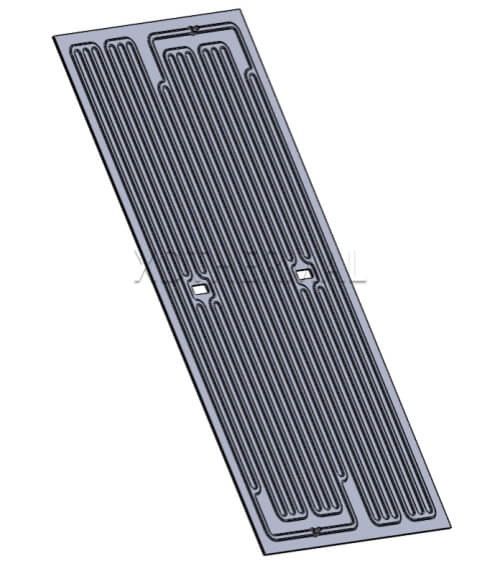
There are several common shapes, each suited to different conditions:
● U-shaped channels: Simple structure, low resistance—ideal for systems with low heat loads or less demanding thermal management needs.
● S-shaped channels: Longer paths and more uniform heat transfer—suitable for applications requiring tight temperature control.
● Serpentine or parallel branch designs: Better for medium to large PVT cooling plates, as they enhance heat transfer while keeping pressure drop manageable.
Choosing the right structure requires considering the plate size, heat load distribution, and the overall flow rate requirements of the cooling system.
We typically run thermal and flow simulations during the early design stages to identify potential problems.
For instance, one of our projects initially used a standard straight S-shaped channel. But simulation showed inadequate cooling in the middle section and clear heat accumulation. After redesigning it into a parallel serpentine layout, the temperature differential across the plate dropped from 12°C to 5°C, significantly improving heat transfer efficiency.
These improvements are often invisible to the naked eye, which is why simulation is such a valuable design tool.
Ultimately, a design has to be manufacturable. That means the flow channel structure must align with production capabilities:
● Straight or S-shaped channels are better suited to extrusion processes. Extrusion cooling plates can be formed in one step, offering uniform channels and high efficiency.
● Complex curves or asymmetrical structures are more compatible with stamping + brazing. This approach allows for higher design flexibility while maintaining good sealing performance.
If a design doesn’t match the manufacturing process, the final product may be too costly, hard to produce, or lack consistency and reliability.
Beyond the flow channel shape, the layout of those channels also plays a major role in how well a PVT liquid cooling plate performs. For example, thermal uniformity depends heavily on whether the system can remove heat evenly and quickly. Localized overheating not only lowers efficiency—it can also shorten the lifespan of the PV cells.
In real-world designs, we usually start by looking at:
● Heat load distribution: If the panel receives uneven sunlight, the channels shouldn’t be uniformly spaced. Instead, we adjust the channel density to concentrate cooling where the heat is highest.
● Inlet and outlet placement: These directly affect flow patterns. Poor placement may result in insufficient contact time in some areas, causing the front to stay too cool while the back overheats.
● Channel length and pressure drop: Longer paths may be needed for even cooling, but they increase system resistance. For some projects, we switch to parallel branches to reduce pressure while keeping heat removal balanced.
I remember one case where our original single-channel design led to an 8°C temperature difference across the plate. By redesigning it with equal-length dual parallel channels, we brought the difference down to 3.5°C and improved overall heat efficiency by about 12%. The results were especially noticeable under high ambient temperatures.
All in all, the layout of the PVT heat exchanger isn’t just about cooling performance—it’s about long-term system stability and effective thermal recovery. Every design decision has lasting consequences.
Let’s also talk about materials and manufacturing, which I believe are often underestimated but critical. A cooling plate’s performance often hinges on whether you chose the right materials and methods from the start.
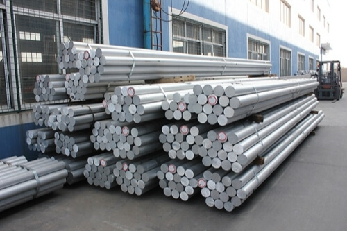
We primarily use aluminum alloys—for good reason. They offer great thermal conductivity, are easy to machine, and are cost-effective. Two of the most common choices are:
● 3003 aluminum alloy: Good ductility and corrosion resistance. Ideal for stamping and brazing. Its thermal conductivity in the H12 temper is around 162 W/m·K.
● 6061 aluminum alloy: Higher strength and slightly better thermal conductivity at around 167 W/m·K. Best suited for extruded cooling plate structures, especially where load-bearing or installation strength is required.
Of course, choosing the material is just the first step. The real challenge is pairing it with the right manufacturing process. Each channel type demands a suitable method:
● For relatively uniform, straight-through channels, extrusion is ideal. It’s efficient, reliable, and perfect for scalable production.
● For complex, multi-branch, or asymmetrical flow paths, stamping + brazing is the way to go. This process offers flexibility for intricate channel layouts and meets advanced thermal management needs.
Whether or not the PVT cooling plate performs well in real conditions depends heavily on these material and manufacturing decisions. You can’t just draw a good design—it has to be built properly, down to every detail.
After covering so much, the truth is that there’s no single template for designing a PVT liquid cooling plate. Each project has its own environmental conditions, heat sources, and spatial constraints. That’s why channel design needs to be tailored to actual working conditions.
From what I’ve seen in practice, even minor adjustments in flow direction or density can make a real difference. For example, increasing fluid contact area in high heat zones or optimizing pressure distribution at the outlets—these small tweaks can significantly improve heat extraction.
The closer the channel design aligns with the thermal distribution, the higher the heat exchange efficiency, the lower the temperature variation, and the more stable the system becomes. And that’s where custom design truly proves its worth.
Looking back, a great PVT cooling plate isn’t just about having the right specs. It’s the result of thoughtful design, well-chosen materials, and practical manufacturing. From channels to layout, from materials to processes, everything needs to be optimized for real-world application. We’re not copying templates—we’re making trade-offs, tuning details, and finding the best fit. Hopefully, these ideas give you some useful insights as you design your own PVT systems.